ENGINEERING PROJECTS
Airbus A380 CAD Modeling
SolidWorks Surface Design & Assembly
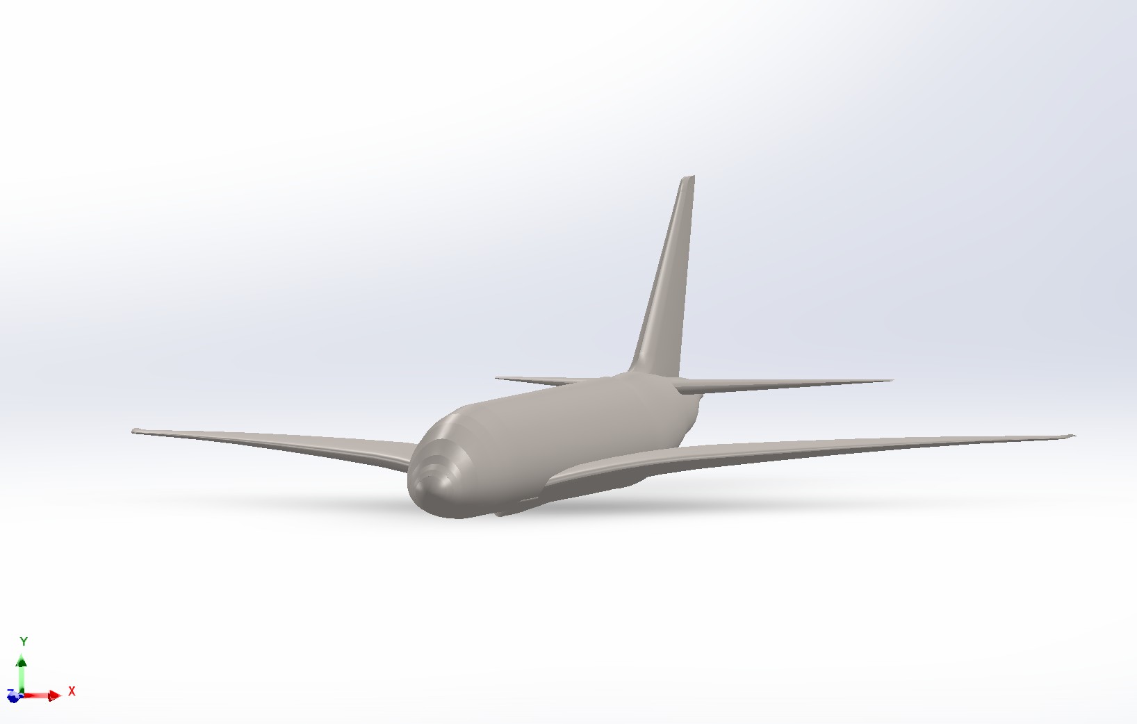
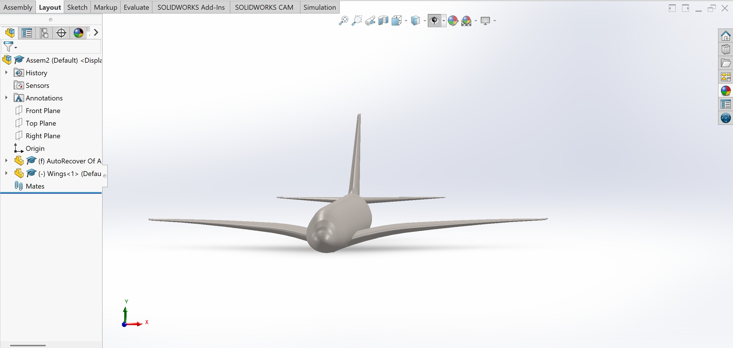
Over the course of the first week of classes after new years, I finished working on modeling the Airbus A380 in SolidWorks with advanced assembly and 3-D sketching followed by lofting the different parts of the aircraft.
I used surface modeling to model the wings and tail of the aircraft in 3-D. As this model doesn't include the other parts like the engine and other details of design, I look forward to completing the following over the course of the next few weeks.
Walking Robot
Design & Simulations
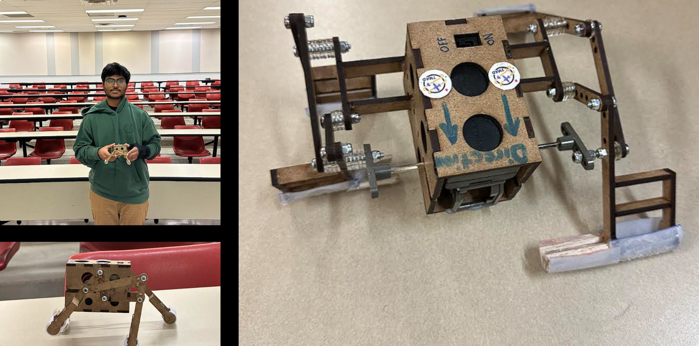
This report showcases the design, development, and analysis of a 4-legged walking robot that utilizes a four-bar linkage mechanism (Crank - Rocker Mechanism). The robot is driven by a motor with a gear ratio of 126, and the maximum speed of the crank configuration was chosen for our particular robot design. The objective of this project was to manufacture/design a robot capable of walking efficiently while showcasing the stability of the mechanical linkages.
The research phase of this project explored three distinct mechanical designs from which our group had to choose for manufacturing the robot:
- A Double Crank-Rocker Mechanism
- A Crank-slider Mechanism
- A Crank-Rocker Mechanism
The designs were analyzed and evaluated using MATLAB coding for their simulation and a weighted design matrix was developed for showcasing manufacturability, performance, and adaptability of the designs. Among all the design configurations, Design 1: The Double Crank-Rocker Mechanism showcased excellence in speed, simplicity, and minimal material usage scoring the highest score in the comparative design matrix.
The selected design features a six-bar linkage that is composed of two synchronized four-bar linkages, phased 180 degrees from each other enabling a crawling-like motion. The mechanical configuration ensured that one leg of the robot maintained contact with the ground during its motion, which promoted continuous stability. The system was analyzed by simulating the mechanism on MATLAB which gave us the displacement, velocity, and the angular velocity of the legs during the motion of cranking and rocking.
The links of the robot were 3-D modelled using CATIA V5 which gave us visual information on the positions of the linkages and the distance between every part of the robot. Once the model was finalized it was laser cut onto an 8mm x 8mm MDF (Medium-density fibreboard) sheet. The motor was encased in a casing that provided structural integrity giving it stability whilst minimizing the use of resources. The battery and the motor were friction fit in the casing, reducing the weight of the glue that would be used.
This project demonstrates how careful mechanisms selection and its analytical modelling should be for creating a functional prototype that can lead to a functional robotic system capable of navigating terrain whilst maintaining its stability.
Flight Simulator Configuration
Simulation & Control Systems
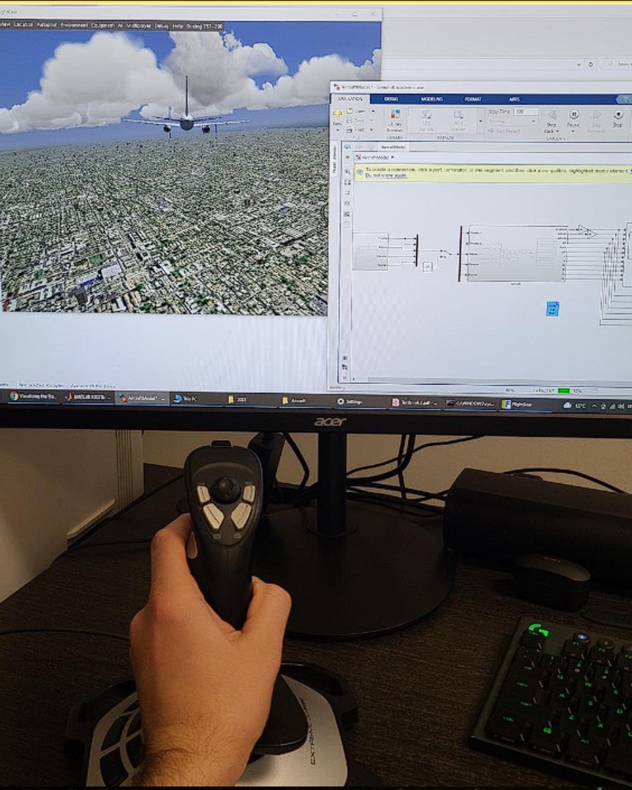
The aviation industry is undergoing rapid transformation, with flight simulators playing an increasingly vital role in pilot training and aircraft development. These simulators require a sophisticated integration of aerospace engineering principles, computer programming, and graphical design to accurately replicate the dynamic behavior of an aircraft in flight. This report documents the design, implementation, and testing of a physics engine for a flight simulator tailored to a new narrow-body twinjet airliner, designed to compete with industry leaders such as the Boeing 737 and Airbus A320 series. The project was made with the primary objective of developing a high-fidelity simulation environment that adheres to real world flight dynamics.
The physics engine serves as the core of the flight simulator, responsible for calculating the aircraft’s motion based on throttle inputs, control surface deflections, and environmental factors. The implementation leverages MATLAB and Simulink to model the aircraft’s six degrees-of-freedom (6DOF) motion, incorporating equations for translational and rotational dynamics, aerodynamic forces, and geodetic navigation. The engine’s outputs include Euler angles, body rates, velocity components, and GPS coordinates, which are visualized using FlightGear and controlled via a joystick interface.
This report is organized into several sections to provide a comprehensive overview of the project. First, the problem statement and objectives are revised and clarified to align with the client’s requirements. Next, the hierarchical structure of the physics engine is presented, detailing the subsystems responsible for force calculations, moment equations, and navigation. The design description elaborates on the implementation of each subsystem, including key equations and Simulink configurations. Design evaluation is then analyzed to validate the engine’s accuracy, followed by a discussion of its integration with FlightGear. Finally, the report concludes with an evaluation of the design’s strengths, limitations, and potential improvements for future iterations.
By bridging theoretical concepts from calculus and dynamics with practical engineering applications, this project not only enhances understanding of flight mechanics but also lays the foundation for advanced aerospace software development. The modular design ensures scalability, while the use of industry-standard tools like MATLAB and Simulink guarantees compatibility with broader simulation ecosystems. Through collaborative effort and iterative testing, the team has delivered a robust physics engine that meets the project’s objectives and prepares the groundwork for further advancements in flight simulation technology.
Industrial Gearbox Design
Mechanical Design & Stress Analysis
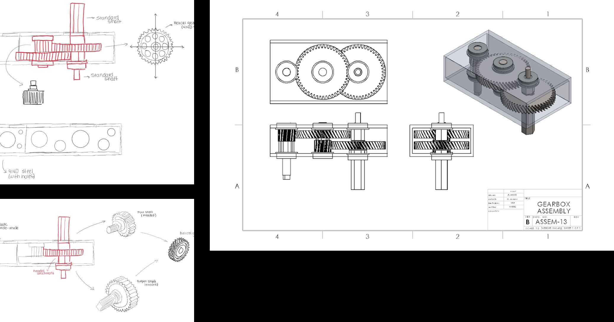
The goal of this project was to design and reverse engineer a gearbox that improves upon the client’s existing product for the robot combat community. The primary goals were to achieve high performance, minimizing cost, and ensuring a well designed product. For design, we needed to maintain the same gear ratio while ensuring the compatibility with the other components of the existing gearbox, as well as considering its assembly, size, shape, and durability. In terms of performance, the gear box had to be efficient, capable of handling high loads, maintaining optimal thermal performance while reducing noise and vibration. Lastly, for cost the selection of material should be affordable and the manufacturing process must stay within budget. I took the role of designing the parts of the gearbox matching the constraints with the real gearbox. I also helped with the designing of the new gear box with the changes researched by the team members.
DA50 RG Aircraft Design
CATIA V5 Surface Modeling
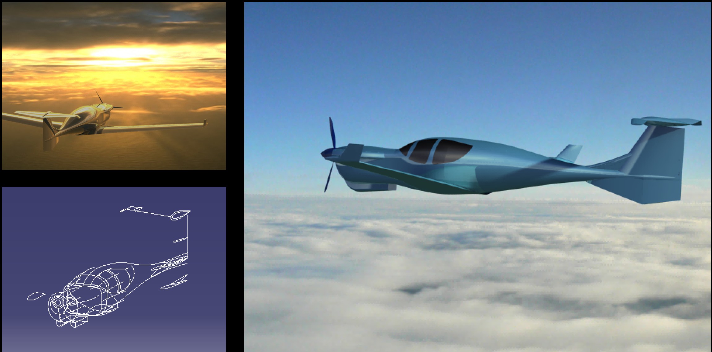
The DA 50 RG Plane Design Project successfully culminated in the creation of a detailed 3D model, reflecting a personal commitment to exploring aircraft design through CAD software. The project achieved its primary goals of applying aerodynamic principles and modeling techniques to construct a representation of the DA 50 RG plane, with accurate dimensions such as a 38.3-feet wingspan and 29-feet fuselage length. The design process, spanning preliminary research, and CAD modeling resulted in a cohesive model that showcases the aircraft's sleek carbon fiber airframe and unique wing and stabilizer design.
Undertaking this project as a self-directed endeavor has been immensely rewarding, offering valuable insights into the complexities of aircraft design and 3D modeling. The challenges of aligning components and refining aerodynamics deepened my technical skills, while the freedom to explore without academic constraints fostered creativity. This experience has not only enhanced my proficiency with CATIA tools but also ignited a passion for further exploring aviation design, with potential future enhancements in mind to refine the model further, and to come explore designing of various other aircrafts, especially military origin ones.
Composite Wing Structure
Materials & Manufacturing
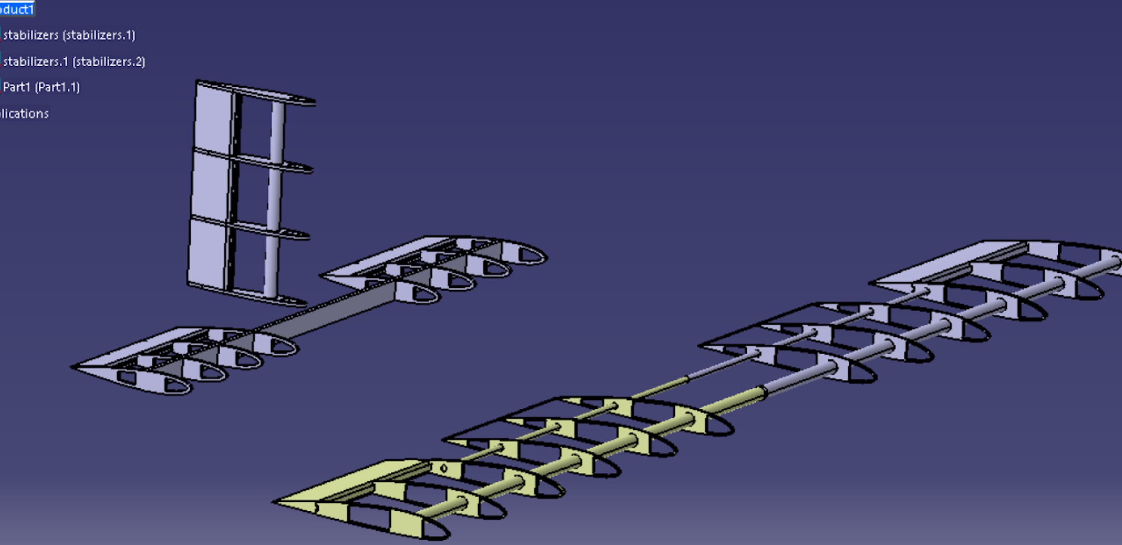
This is the wing design of the aircraft for the RC3 Competition, which was 3-D modelled on CATIA V5. A detailed analysis of the sizing of the wing and the stabilizers was done using the constraints given, and also matching the real life speculations of the wing. This is wing has an aspect ratio of 6 which provides a stable and high lift profile for the airplane. The wing also uses NACA 2412 airfoil which provides the high lift profile property for the airplane and allowing shorter take offs and stable level flight. The internal configuration incorporates spars and ribs, reflecting realistic load distribution and structural integrity. Both horizontal and vertical stabilizers are proportioned for aerodynamic balance and control authority. Emphasis was placed on weight optimization and structural efficiency, creating a design that merges aerodynamic performance with manufacturability and competition readiness.
This project inspired me to design more aircrafts and build on my passion for manufacturing RC planes which aligns with my interest of working in an aircraft manufacturing company as an manufacturing engineer where I could help with the design of the aircraft and also help with manufacturing them on a larger scale.